3 Input 7 Segment Display Truth Table / Bcd To 7 Segment Display Decoder
• driven by a binary coded decimal (bcd) nibble. The internal circuitry and logic gates for the display is shown below. 4 10) using the truth table, the values of the input terminal were changed. 0, 1, 2 and 3 were shown in the seven segment display.

1 2 3 4 5 6 7 8.
Now, are you able to design your decoder circuit using discrete logic ttl/cmos . Inputs a g f b c d e. Application of bcd to display decoder . • driven by a binary coded decimal (bcd) nibble. 1 2 3 4 5 6 7 8. 16 15 14 13 12 11 10 9. • a separate set of combinational logic . • used for output of a single decimal digit. 0, 1, 2 and 3 were shown in the seven segment display. The internal circuitry and logic gates for the display is shown below. Atruth table is constructed with the combination of inputs for each decimal number. Internal circuitry and logic gates for 7 seg . 4 10) using the truth table, the values of the input terminal were changed. When an input is 1, it colors the corresponding segments of the component; .
1 2 3 4 5 6 7 8. When an input is 1, it colors the corresponding segments of the component; . 0, 1, 2 and 3 were shown in the seven segment display. Now, are you able to design your decoder circuit using discrete logic ttl/cmos . The internal circuitry and logic gates for the display is shown below. Application of bcd to display decoder . Internal circuitry and logic gates for 7 seg . • driven by a binary coded decimal (bcd) nibble.

Now, are you able to design your decoder circuit using discrete logic ttl/cmos .
• used for output of a single decimal digit. • a separate set of combinational logic . Application of bcd to display decoder . Atruth table is constructed with the combination of inputs for each decimal number. Now, are you able to design your decoder circuit using discrete logic ttl/cmos . When an input is 1, it colors the corresponding segments of the component; . 4 10) using the truth table, the values of the input terminal were changed. 1 2 3 4 5 6 7 8. Inputs a g f b c d e. 16 15 14 13 12 11 10 9. • driven by a binary coded decimal (bcd) nibble.
Inputs a g f b c d e. • a separate set of combinational logic . Now, are you able to design your decoder circuit using discrete logic ttl/cmos . When an input is 1, it colors the corresponding segments of the component; . Application of bcd to display decoder . • driven by a binary coded decimal (bcd) nibble. 0, 1, 2 and 3 were shown in the seven segment display.

• a separate set of combinational logic .
• used for output of a single decimal digit. 16 15 14 13 12 11 10 9. 0, 1, 2 and 3 were shown in the seven segment display. The internal circuitry and logic gates for the display is shown below. When an input is 1, it colors the corresponding segments of the component; . Inputs a g f b c d e. Now, are you able to design your decoder circuit using discrete logic ttl/cmos . • driven by a binary coded decimal (bcd) nibble. Internal circuitry and logic gates for 7 seg . Atruth table is constructed with the combination of inputs for each decimal number. • a separate set of combinational logic . Application of bcd to display decoder . 1 2 3 4 5 6 7 8. 4 10) using the truth table, the values of the input terminal were changed.
3 Input 7 Segment Display Truth Table / Bcd To 7 Segment Display Decoder. 0, 1, 2 and 3 were shown in the seven segment display. 16 15 14 13 12 11 10 9.
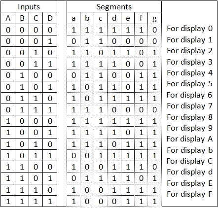
When an input is 1, it colors the corresponding segments of the component; 7 segment display truth table. 16 15 14 13 12 11 10 9.

• used for output of a single decimal digit.

The internal circuitry and logic gates for the display is shown below. • used for output of a single decimal digit. 16 15 14 13 12 11 10 9.

Atruth table is constructed with the combination of inputs for each decimal number.

Atruth table is constructed with the combination of inputs for each decimal number. Internal circuitry and logic gates for 7 seg . Inputs a g f b c d e. • a separate set of combinational logic . 16 15 14 13 12 11 10 9.

Now, are you able to design your decoder circuit using discrete logic ttl/cmos . • driven by a binary coded decimal (bcd) nibble. • used for output of a single decimal digit. Atruth table is constructed with the combination of inputs for each decimal number. When an input is 1, it colors the corresponding segments of the component; .

Atruth table is constructed with the combination of inputs for each decimal number. When an input is 1, it colors the corresponding segments of the component; .

Atruth table is constructed with the combination of inputs for each decimal number.

4 10) using the truth table, the values of the input terminal were changed.

1 2 3 4 5 6 7 8.
Application of bcd to display decoder .
Internal circuitry and logic gates for 7 seg .

When an input is 1, it colors the corresponding segments of the component; .

0, 1, 2 and 3 were shown in the seven segment display.

0, 1, 2 and 3 were shown in the seven segment display.

Post a Comment for "3 Input 7 Segment Display Truth Table / Bcd To 7 Segment Display Decoder"